Manufacturing processesReading time 13 min
Read the Weld Symbol; Inspect Beyond the Bead
A clean-looking bead does not prove a sound weld. The symbol specifies joint type, size and location; inspection must also account for defects and distortion that appearance alone cannot reveal.
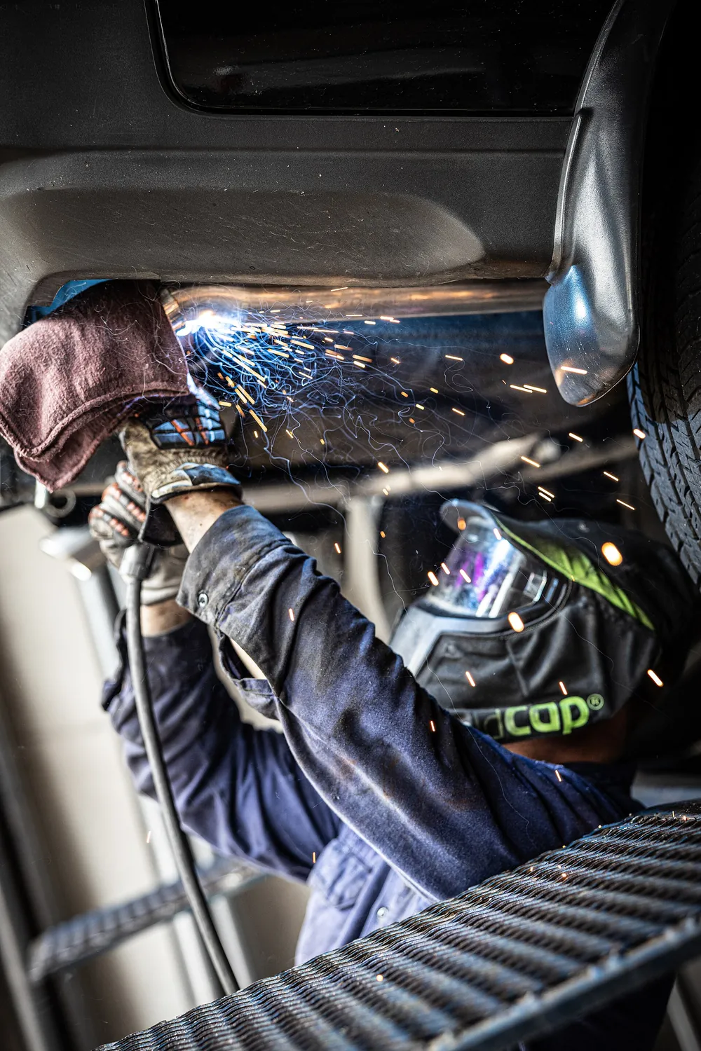 Wikimedia Commons・Gas Metal Arc Welding (Mig).jpg・CC BY-SA 4.0
01Parts of a weld symbol
An ISO 2553 weld callout combines an arrow, a reference line and a weld symbol. Their positions tell the welder where the joint is and which side receives the weld. Read the whole callout before interpreting size or length.
- Symbol on the solid line: weld on the arrow side.
- Symbol on the dashed line: weld on the other side.
- Symbols on both: welded from both sides.
- The tail (fork): process code (135 = MAG, for example), specification number, filler and quality level.
| Symbol | Weld type | Typical use |
|---|---|---|
| Triangle | Fillet | T joints, lap joints, corner joints |
| V | Single-V butt | Full penetration butt welds in medium plate |
| Y | V with a root face | Where root penetration must be controlled |
| U | U groove | Thick plate, less filler needed |
| Semicircle (plug) | Plug or slot weld | Fixing overlapping plates |
| Circle at the elbow | All-round weld | A closed loop |
| Flag | Field weld | Site assembly |
How to read the sizes
For a fillet weld, a gives the effective throat and z gives the leg length. Intermittent-weld callouts also specify segment length and spacing. Read those dimensions using the notation of the governing standard; a small symbol change can alter the amount of weld required.
02Defects you cannot see
| Defect | Position | Main cause | Why it matters |
|---|---|---|---|
| Porosity | Internal or surface | Poor shielding, moisture or oil on the parent metal | Reduces effective section |
| Slag inclusion | Internal | Interpass cleaning not done properly | Stress concentration |
| Lack of fusion | Internal | Insufficient current, wrong angle | Extremely dangerous, behaves like a crack |
| Incomplete penetration | Root | Groove too shallow, root gap too small | Effective thickness not achieved |
| Undercut | Surface | Excessive current, travel speed too high | A fatigue initiation site |
| Crack | Internal or surface | Restraint stress, hydrogen embrittlement, hardened parent metal | The most serious of all |
Lack of fusion and incomplete penetration can reduce the load-bearing section while remaining hard to see from the surface. Critical joints may require ultrasonic or radiographic testing in addition to visual or surface methods, according to the design requirement.
Quality levels
ISO 5817 defines quality levels for specified fusion-weld imperfections. A level such as B, C or D sets acceptance limits by defect type; it does not replace the need to state the inspection method and extent.
03Managing distortion
Welding heats one region and lets it cool while neighboring material restrains it. The uneven contraction can bend or twist the part, especially in thin sections.
- Angular distortion. The two sides of a butt weld lift, because the weld pool is wider at the top and contracts more.
- Longitudinal bowing. A long bead contracts along its length and bows the whole part.
- Shrinkage. Overall size reduces; a long bead can pull more than 1 mm per metre.
Plan the sequence and fixturing before welding. Symmetric passes, backstep techniques or presetting may reduce distortion, but each has to suit the joint. Straightening afterward adds work and can introduce new stresses.
04Inspection before automation
Automation helps repeat and record welding conditions, but stable settings require measured results. Capture bead geometry and relevant defect data first, then use those measurements to tune the process.