Machine elementsReading time 13 min
Reading the Gear Data Table
A gear outline does not tell you whether two gears will mesh. The data table does: module, tooth count, pressure angle and accuracy requirements. Read those values before judging the drawing.
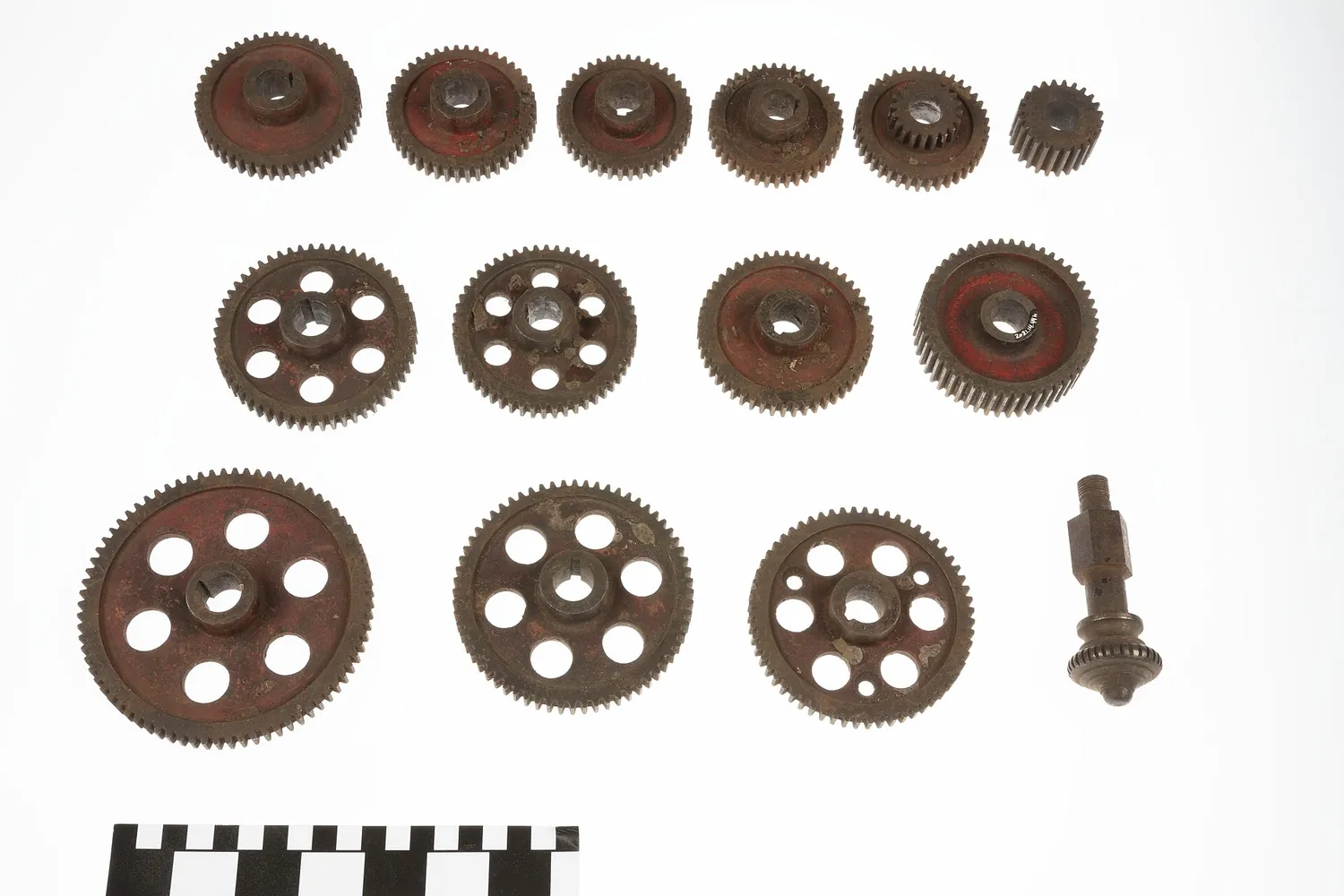 Wikimedia Commons・One Knobbed Gear Shaft and Thirteen Spur Gears・Public domain
01Why the outline is simplified
A gear's tooth profile is generated from its design parameters, not measured from the simplified outline on the drawing. The tip, pitch and root circles help orient the reader; module, tooth count, pressure angle and other values in the data table define the gear.
02Reading the data table
| Parameter | Symbol | Meaning |
|---|---|---|
| Module | m | Pitch diameter ÷ tooth count; sets the size of the teeth |
| Number of teeth | z | How many teeth in one revolution |
| Pressure angle | α | The reference angle of the involute; 20° is standard |
| Tooth system | — | Full depth or stub; sets the addendum coefficient |
| Profile shift coefficient | x | How far the cutter is moved relative to the pitch circle |
| Pitch diameter | d | d = m × z |
| Tip diameter | da | da = m(z + 2) for a standard spur gear |
| Root diameter | df | df = m(z − 2.5) for a standard spur gear |
| Span measurement / measurement over pins | W / M | The dimension actually accepted |
| Accuracy grade | — | Grade 6 or 7 to ISO 1328, for example |
03Center distance and ratio
For a standard pair, center distance is a = m(z₁ + z₂) / 2 and ratio is i = z₂ / z₁. A mechanism may fix the available center distance, so the designer must choose compatible module, tooth counts and any profile shift together.
Profile-shifted gears
Profile shift changes how the cutter meets the gear blank. It can accommodate center distance, reduce undercut on a small tooth count and rebalance tooth strength. When a shift coefficient is specified, use the corrected geometry rather than standard-gear dimensions.
04Measuring tooth thickness
You cannot grip the pitch circle directly with ordinary calipers. In practice, tooth thickness is checked through measurements such as span, over-pins or chordal thickness, each with its own setup.
| Method | What it measures | Typical use | Limitation |
|---|---|---|---|
| Span measurement W | Distance between two parallel faces spanning k teeth | Spur and helical gears | Needs enough face width and enough teeth |
| Measurement over pins M | Outside distance with two pins inserted | Low tooth counts, internal gears | Requires pins of the right diameter |
| Gear tooth caliper | Chordal thickness at a specified height | Quick checks on the floor | Affected by tip circle error |
05Accuracy and flank error
ISO 1328 grades gear accuracy by several distinct tooth and flank errors. The grade number alone is not a measured result; read which characteristics and test method the drawing specifies.
- Profile deviation fα. How far the real flank departs from the theoretical involute.
- Helix deviation fβ. Tilt or crowning of the flank across the face width.
- Single pitch deviation fp and cumulative pitch deviation Fp: whether the teeth are where they should be.
- Radial runout Fr. Eccentricity of the tooth ring relative to the axis.
A tighter accuracy grade generally means more controlled cutting and inspection, and sometimes finishing after heat treatment. Compare the required grade with the transmission's function before adding cost.
Distortion from heat treatment
Heat treatment can distort the flanks. For a high-accuracy, case-hardened gear, the route may include hobbing, heat treatment and gear grinding. That finishing operation belongs in the quote, not as a surprise after the parts are made.