Manufacturing processesReading time 13 min
How to Set Cutting Conditions That Hold Up on the Shop Floor
Speed and feed are not numbers to copy blindly from a catalogue. Tool life, cycle time, finish and machine rigidity all pull the setting in different directions. Start with the constraints that matter for this job.
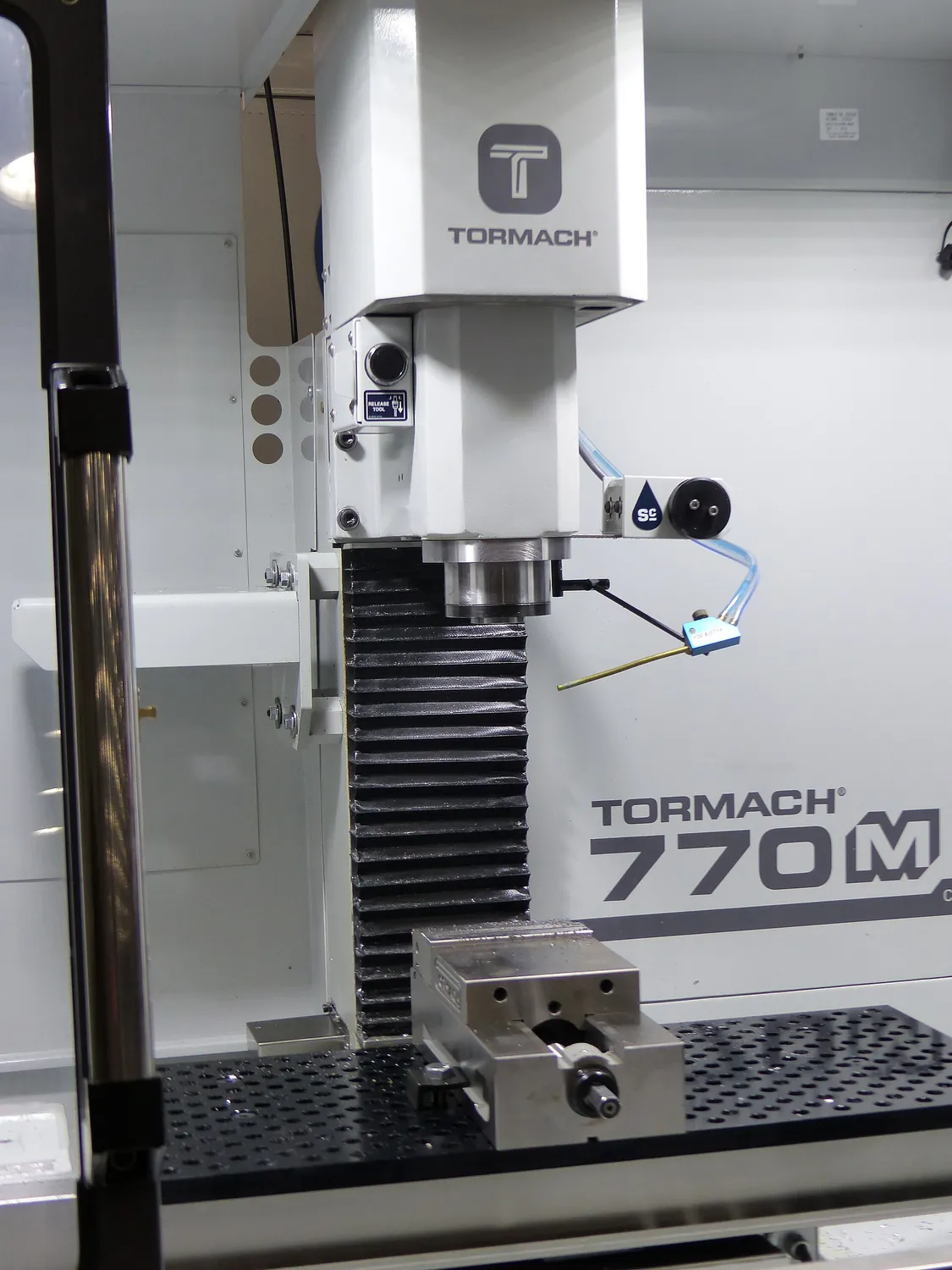 Wikimedia Commons・CNC Mill 1.jpg・CC BY-SA 4.0
01Speed, feed and depth
| Parameter | Symbol | Formula | Decides |
|---|---|---|---|
| Cutting speed | Vc (m/min) | Vc = π × D × n ÷ 1000 | Tool life, cutting temperature |
| Spindle speed | n (rpm) | n = Vc × 1000 ÷ (π × D) | Derived from Vc |
| Feed per tooth | fz (mm/tooth) | fz = Vf ÷ (n × z) | Chip thickness, finish, chip breaking |
| Feed rate | Vf (mm/min) | Vf = fz × z × n | The value actually sent to the machine |
| Axial depth of cut | ap (mm) | — | Productivity, axial force |
| Radial depth of cut | ae (mm) | — | Radial force, vibration, engagement angle |
Material removal rate gives a quick productivity measure: MRR = ap × ae × Vf ÷ 1000 in cm³/min. Yet the same MRR can come from a deep, slow cut or a shallow, fast one. Tool load, chip removal and part deflection will not be the same, so MRR alone cannot set the cutting conditions.
02Cutting speed and tool life
Taylor's tool-life equation, Vc × Tⁿ = C, captures a practical trade-off: as cutting speed rises, tool life falls. The constants depend on the tool and work material, so use them as a guide for trials rather than a universal setting.
| Materials | Carbide end mill Vc (m/min) | Notes |
|---|---|---|
| Aluminium 6061 | 300 ~ 1000 | Built-up edge is the enemy, so speed should be high |
| Low-carbon steel S45C | 120 ~ 200 | The usual benchmark |
| Stainless SUS304 | 80 ~ 140 | Work-hardens badly; the cut must not be too light |
| Cast iron FC250 | 100 ~ 180 | Chips break well but it is abrasive |
| Titanium Ti-6Al-4V | 30 ~ 60 | Poor conductivity; the heat stays in the edge |
| Hardened steel HRC50+ | 50 ~ 120 | Needs CBN or ceramic tooling |
03Feed per tooth
Very light feed can be just as harmful as heavy feed. If the chip is thinner than the cutting edge can shear, the tool rubs and heats the surface instead of cutting cleanly. Check the minimum chip thickness as well as the finish target.
- Lower limit. fz should not fall below the cutting edge radius, generally 0.02 to 0.05 mm.
- Upper limit. Set by tool strength, machine power and the surface finish required.
- Surface finish. In turning the theoretical value is Rz ≈ f² ÷ (8 × nose radius), so a larger nose radius gives a better finish at the same feed.
Chip thinning
At a small radial engagement, the effective chip thickness can be lower than the programmed feed per tooth. This chip-thinning effect is why a high-speed milling path may need a higher programmed feed even while the radial depth is reduced.
04Depth of cut and vibration
| Strategy | ap | ae | Where it fits |
|---|---|---|---|
| Conventional milling | Small (0.5–2 mm) | Large (0.5–1 D) | Ordinary machine rigidity, roughing |
| High-speed machining | Large (1–2 D) | Small (5–10% D) | Rigid machines, deep pockets, hard material |
| Trochoidal | Large | Small, on a looping path | Slotting, avoiding full engagement |
Chatter is a stability problem, not simply proof that the feed is too high. Changing spindle speed, engagement, tool overhang or fixturing may move the process out of the unstable range; slowing every parameter is not always the best response.
05Adjusting catalogue values
- Catalogue conditions assume a rigid machine. An older machine, a long tool holder or a thin-walled part all force the usable parameters well down.
- The coolant does not match. The same tool has a completely different Vc ceiling dry, with air, or with soluble coolant. Some coatings chip from thermal shock if flooded during interrupted cutting.
- Overhang gets ignored. Double the tool stick-out and deflection increases roughly eightfold, it is a cubic relationship.
- How the part is held. A parameter set that runs happily in a vice can push the part straight off a vacuum chuck.